MQTT Garage Door Opener
We recently moved into a house that had dumb garage doors, its the first house I have lived in that had any sort of garage door and it came with a level of worry that they would be left open at some point. It was also inconvenient to need to share 2 remotes between 4 different people. I decided to make a little module to control the doors and have positional sensors on them to remotely see if they were open or closed.
Step 1: Research
The first thing I had to do was figure out how this module needs to interact with the garage door opener. There are three terminals on the back of it that correspond to:
Button: the terminal that the open/close button is connected to
Common: the common pin
24v: goes between the optical safety sensors and common
The button and common pins are pretty self explanatory, I connect a relay between them to act as the button. The other terminal, 24v, is less obvious. The safety sensors are wired between common and 24v, how do they send the fact that they have been tripped back to the garage door opener to stop closing?
It turns out that the 24v pin is not actually 24 volts, but more like 5 volts. The line pulsates at around 20KHz when the sensors are not tripped. When they do trip, this signal stays high. To detect that the sensors have tripped we just need to see when the signal stops changing state with a little bit of circuitry to protect our delicate microcontroller in case the line does reach 24v at some point.
Step 2: Planning
Now that I know what the module needed to do, I need to figure out how I want it to do that. A relay for the button is a nice easy way to act as a button, but I need some protection circuitry on the heartbeat signal from the safety sensors. I decided to use opto isolators as input protection circuitry, simply because I don't use them very often and I think they are cool. Resistors with (or without) a zener diode would have been perfectly sufficient.
I initially wanted to use an ESP8266 because I have a lot of them lying around, but the amount of GPIO available on it is limited, and some of the pins available are responsible for internal functions (thus some cant be used for input, some for output, some cant be high at boot, etc...). The ESP32 has much more GPIO available, enough for all the features I want, including:
- Relay control pins x2
- Relay sense pins x2
- Safety sensor heartbeat pins x2
- Position sensor pins x4
The relay sense pins are just so I can determine if the relay actually actuated, turning an open loop system into more of a closed loop system.
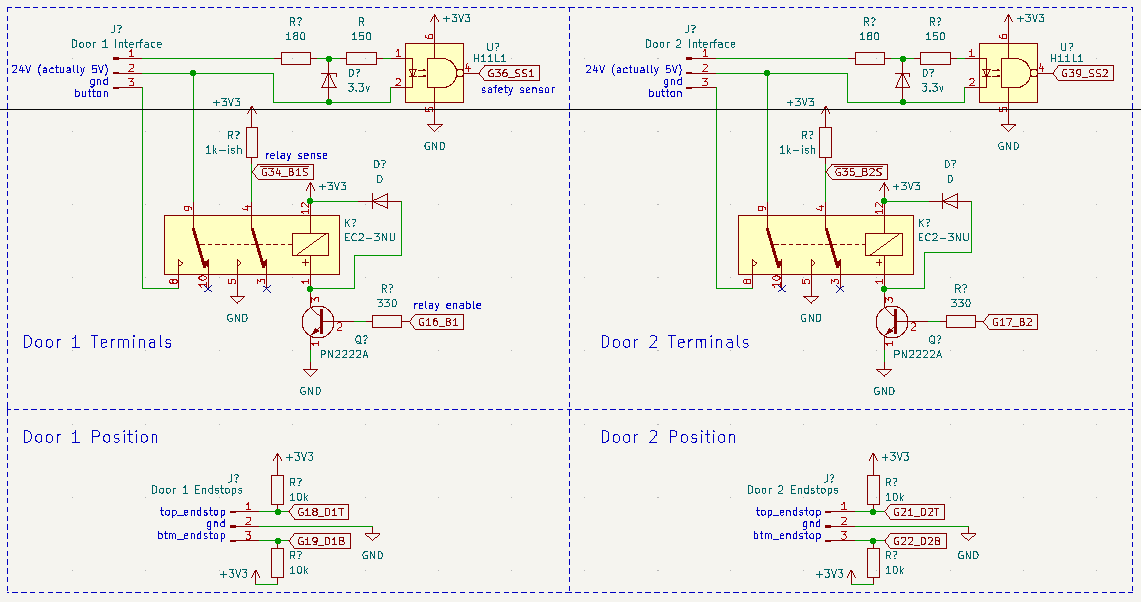
This is the schematic I came up with, sadly this is not what the final product ended up being.
Step 3: Prototype
I made up the opto isolator circuit on a breadboard and used an Arduino to output a 20KHz square wave for testing. It was not acting as I expected. After too long to admit, I read over the datasheet for the opto and found that it is an open collector output. This means that when the output is true, it pulls the output line to ground. I added a pull up resistor and everything looked good.
I decided that everything else was simple enough and would work, so I soldered up the board and found that the relays did not work. I had scavenged them from something else, sad. Instead I used relay modules and made the footprint of this module bigger than I wanted to, but its just a prototype, right? This is temporary. (hah)
I modelled a quick little enclosure and printed it out to hold everything in place and keep it safe, then secured everything inside.
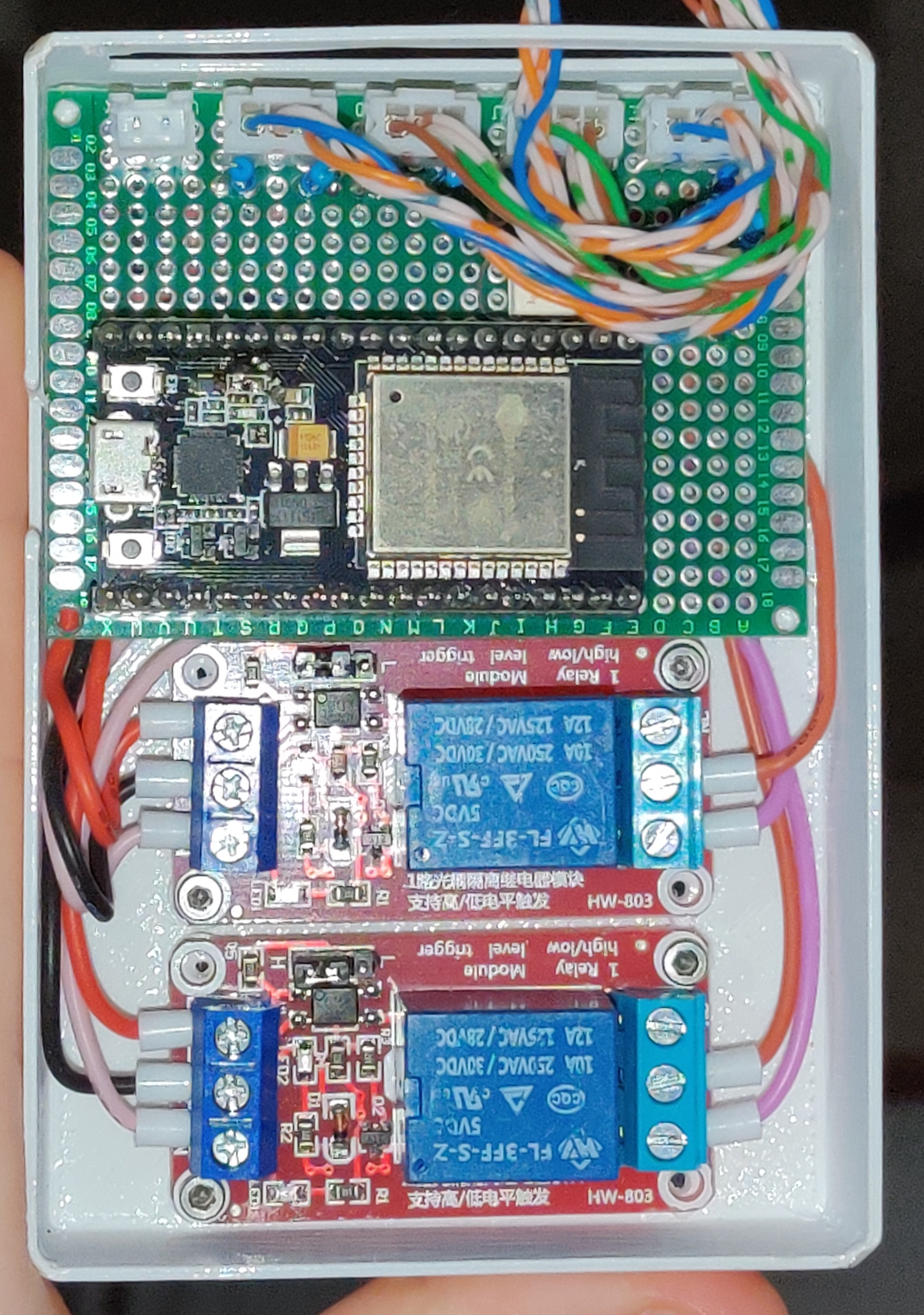
The position sensor wires had to be pretty long, and the only wires I had that were long enough were CAT5 cables. I split some open and used the wires. They crimp pretty nicely in a JST style crimp, I even got two wires to fit into one crimp. We will talk about the positional sensors later.
Step 4: Programming
Now that we have hardware, we need to write some firmware to tell that hardware what to do. My preferred IDE is VScode, and with the PlatformIO extension its quite easy to write firmware using the Arduino framework (although there are many others supported).
I wrote some code that connected to wifi, MQTT, interrupts for the input pins, some timers for the safety sensor heartbeat detection, blah blah blah. Lets get to the fun stuff, MQTT Discovery with HomeAssistant!
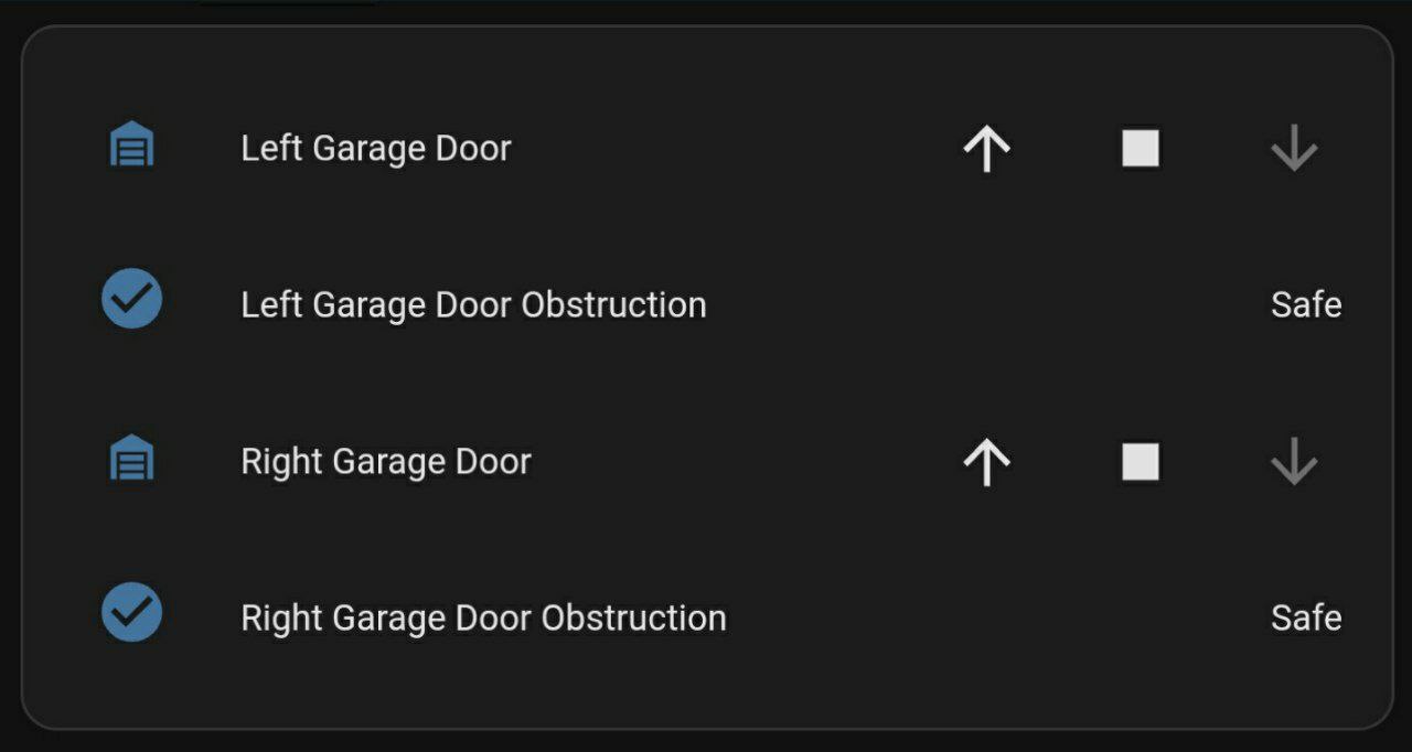
HomeAssistant!
If you arent familiar, HomeAssistant is a home automation program that you can host locally and connect devices to. It allows you to set up automations, actions, scenes, and just control everything from a local server where you can have piece of mind that your data is not in the hands of The Zuck or any other Bozos. It lets you manage all your devices from one central location.
There are two ways to add an MQTT device to HomeAssistant; via the configuration file or via MQTT discovery. Using the configuration file, you would specify all the different topics that the device would use, what the payloads mean, what the device is, everything like that. With MQTT discovery, you do the same exact thing except it is sent to an MQTT topic in a JSON string.
Using MQTT we also have the ability to specify a will message which will be sent to a topic when the device disconnects. This is useful for specifying if the device is available using the availability topic in the HomeAssistant configuration for the device.
The discovery I came up with for my cover and safety sensor entities looks like this:
// Garage Door:
{
"~": "homeassistant/garage/garage_doors/",
"cmd_t": "~/left/cmd",
"stat_t": "~/left/state",
"availability_topic":"~/available",
"name": "Left Garage Door",
"uniq_id": "left_garage_door",
"dev_cla":"garage",
"device": {
  "sw_version": "v1.0",
  "identifiers": ["GDO_v1.0_SN1"],
  "manufacturer": "DM & ZZ",
  "name": "Garage Door Opener"}
}

// Safety Sensor:
{
"~": "homeassistant/garage/garage_doors",
"stat_t":"~/right/safety",
"availability_topic":"~/available",
"name":"Right Garage Door Obstruction",
"uniq_id":"right_garage_door_safety",
"pl_off":"safe",
"pl_on":"triggered",
"dev_cla":"safety",
"device": {
  "sw_version": "v1.0",
  "identifiers": ["GDO_v1.0_SN1"],
  "manufacturer": "DM & ZZ",
  "name": "Garage Door Opener"}
}
The keys may look a bit funky, I used a mix of the shortened prefixes and full length keys. I'll make an article explaining the basics of using MQTT discovery and HomeAssistant in the future where I give a better explanation on how everything works.
Step 5: Positional Sensors
The positional sensors were a little bit of a challenge to add, and I went through a few iterations before finding a design that worked reliably.
My first design was a platform command stripped to the door, with a microswitch mounted to the rail. This did not work because I had it mounted too high on the door and it failed rather explosively. I wish I had taken a video. The panels of the door cut across the middle of the bend when it is opening/closing. Luckily there was no damage to the door.
I then moved the assembly down, but the command strip kept failing.
After that, I decided to use the very top guide wheel bushing, I made a sleeve that clipped over it and mounted the microswitch on the bend. If you had read the first prototype attempt, I'm sure you realise what happened. It exploded off the door again.
After this, I kept those sleeves on to use as the open positional sensor as there is not interference there. I made another sleeve that fits over a lower bushing, and this attempt kinda worked! The only issue was that the sleeve kept rotating and it would not trigger the positional sensor, meaning the door was floating in limbo.
I revised the design of the sleeve to prevent it from slipping, and if it did it would still trigger the microswitch.
All Done!
but not really. I still want to add some software features, like detecting when the homeassistant availability topic changes and resending MQTT discovery if it restarts. I do not retain my discovery messages because its quite annoying in my experiences.
I also want to make physical buttons that interact with Home Assistant to open the doors instead of using the app.
Maybe a little bit of a smarter algorithm that takes commands into account for the position of the door instead of pure positional sensor input.
As we all know, these things never really end. I am happy to say that this prototype is now functional, even though its not done.